Description
LE PONT : Didactic Approach for Engineering Science
The Original Bridge :
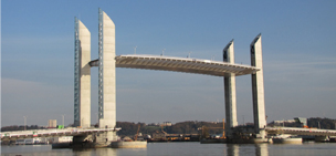
The Chaban-Delmas bridge was inaugurated in 2013 in Bordeaux, a well-known town in Southwestern France. The aim of the bridge was to join the urban boulevards of Bordeaux, by connecting two districts called Bacalan and Bastide.
With a length of 433 m, the bridge has 2 lanes for public transport, 4 lanes for road vehicles, and 2 gateways for cyclists and pedestrians.
The fixed spans are made from metal beams on concrete piles.
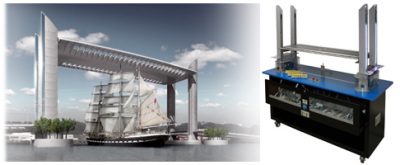
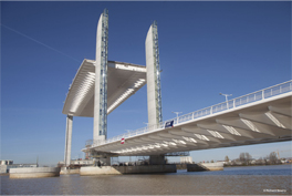 Four concrete towers of 75 m high allow the central lift span (length 117 m) to provide 50 m clearance for boats sailing towards the historic centre.
The central lift span, weighing 2700 tons and produced in metal housing, is balanced by 4 counterweights of 640 tons each.
It is powered by 2 synchronized 132 kW engines, and can be lifted on load in 12 min.
The lift span’s height is controlled by a sensor inside each tower. He control panel, located on the left river bank, allows to monitor traffic, activate the engines and control the passage of boats.
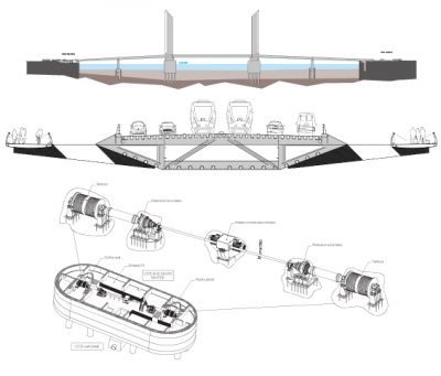
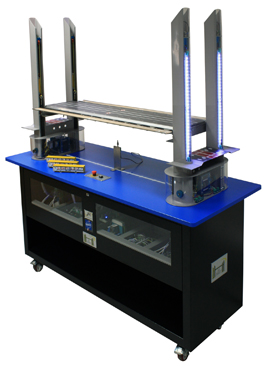
The Civil Engineering Mock-Up :
Structure
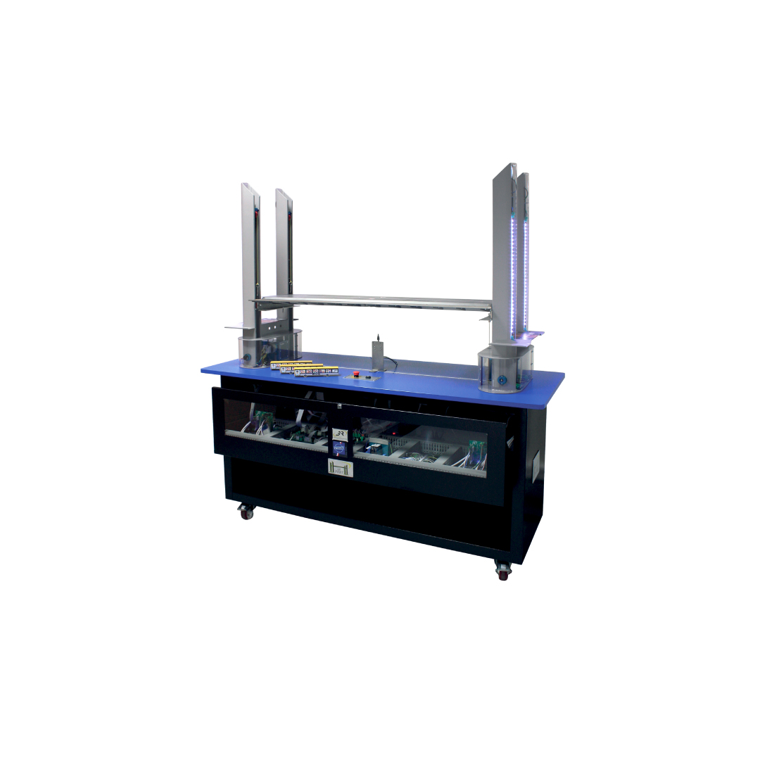
- Mock-up at 1/100th scale
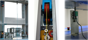
- Structure of the bridge piles made of lacquered steel with thickness 1.5 mm closed by polycarbonate for visualization of the cables and counterweights
- Pulleys and counterweights on each pile with Kevlar cable
- Identification of the cables by colour: yellow for lifting, blue for retrieving
- Bases of the bridge’s piles composed of motor and gear-motor power 25 W
- Cables winding winch with spooling groove
- Box-type apron made of steel thickness 0.5 mm
- Mounting of the bridge on a cabinet with casters
Instrumentation:
- 1 potentiometric sensor for measuring arrow
- 4 effort sensors on pulleys
- 3 incremental encoders
- 4 apron force sensors

- 2 sensors at apron’s height (cable sensors)
- 4 current consumption’s sensors
- 2 power voltage measurements
Control system:
- WINDOWS laptop environment
- LABVIEW display software
- Connection via USB
Control Software:
- To configure:
- The control system
- The measurement channels and the calculated channels
- The activities
- To measure:
- Acquire, store in a file, or recover measures
- Perform channels calculations
- To analyse:
- View graphs
- Determine the characteristic values using sliders
- Play educational animations
Proposed Activities :
“MATERIAL” Activity
M-1 Geometry of the lifting span : Study of the geometrical characteristics of the central box through modelling
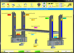
M-2 Resistance of the lifting span : Study of the deformation of the apron on load, with different masses. Measurement of the arrow, computation of the constraint of the apron under load.
M-3 Resistance of the lifting cables : Study of the cables resistance allowing the lifting of the the apron
“ENERGY” Activity
E-1 Kinematics of transmission : Study of kinematics of apron lifting: determining the reduction ratio, the winding diameter, from position or speed measurements.
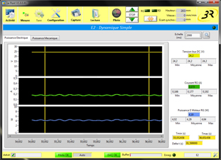
E-2 Simple dynamics : Study of simplified balance of the span lifting power under load. Determining the overall yield from power measurements
E-3 Complete dynamics : Study of the detailed balance of the span lifting power under load. Determining intermediate power measurements and yields.
E-4 Accelerated motion : Dynamic study of the lifting span under load. Power measurement during acceleration and determining yields.
E-5 BLDC motor : Study of electronic switching of a brushless motor depending on the encoder information.
E-6 Friction : Power balance of the reducer in the presence of dry and viscous frictions. Measuring torques and yields, determining constant friction.
E-7 Identification : Identify the response in speed of batteries motors. Determining the mock-up parameters.
“INFORMATION” Activity
I-1 Incremental encoder : Study of an incremental encoder. Determining the position and speed rotation from measuring signals.
I-2 Absolute encoder : Study of a synchronous serial link. Determining the decoding method.
I-3 Tachometer sensor : Study of an analogue tachometer sensor. Signal measurement and synthesis of the optimal filter.
I-4 Gauges sensor : Study of an analogue device for measuring short displacement. Determining the gauges bridge constants.
I-5 Fieldbus : Study of an asynchronous serial link. Determining the decoding method.
I-6 Adjusting the synchronization : Study of the battery speed control to synchronize the movements of the two banks. Determining adjustment parameters.
I-7 Deck lighting control : Programming of the colours coding and synchronous serial link on micro controller
I-8 Coders reading : Programming of the decoding of the absolute and incremental coders signal on a micro controller.
I-9 Potentiometric sensor : Study of the displacement measurement by two technologies of potentiometric sensors. Determining calibration coefficients.
I-10 Programming of synchronization : Programming the batteries speed control to synchronise the movements of the two banks, from the heights and speeds measured of the instructions of each bank.